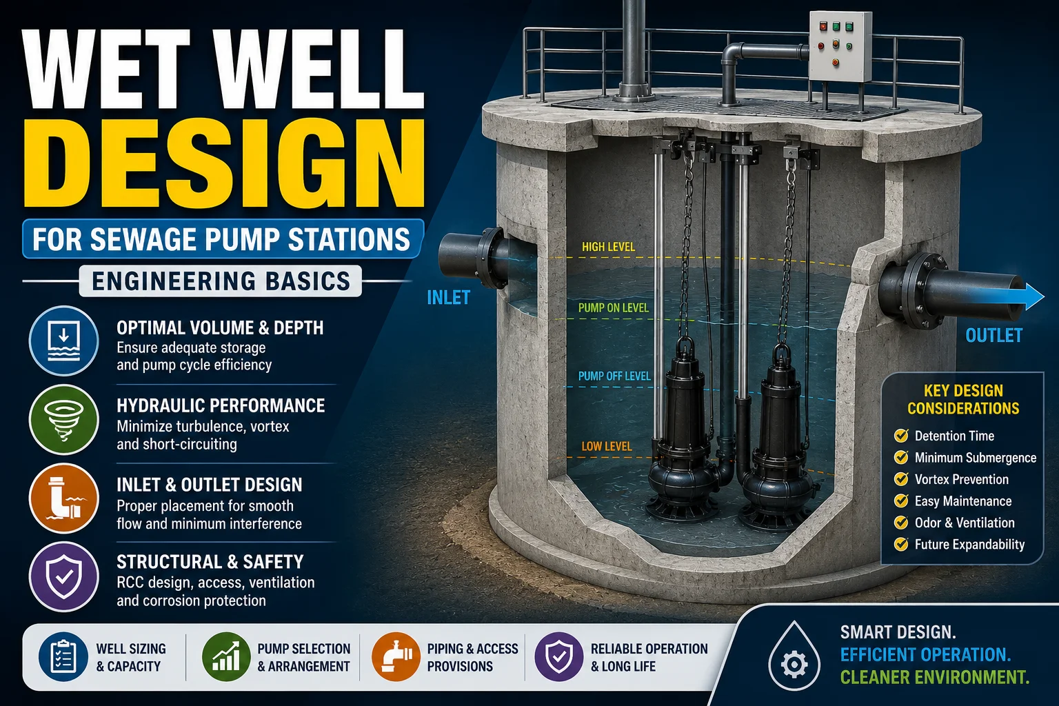
Learn wet well design basics for sewage pump stations, including storage volume, cycle time, submergence, inlet conditions, and common mistakes.
A sewage pump wet well is not just a pit below the ground. It is a hydraulic buffer, a solids-handling chamber, and a control point for pump starts. If the wet well is too small, pumps short-cycle and wear faster. If it is too large, sewage becomes stagnant and solids settle in unwanted zones. The best design balances usable storage, pump cycle time, inlet conditions, and maintenance access. For most stations, engineers should size the wet well around the pump operating range rather than around the civil footprint alone. That means checking inflow, pump capacity, run time, starts per hour, and the minimum level needed to protect the pump suction. The result should be a sump that drains predictably, avoids turbulence, and keeps sewage moving toward the pump in a controlled way. For practical pump selection support, see the Flow Chem Pumps guide on the submersible sewage sludge pump.
Good wet well design also affects energy use. A station with unstable inflow or poor inlet geometry can force pumps to work against swirling flow and intermittent air pockets. That raises vibration, lowers hydraulic efficiency, and increases maintenance. For engineers, wet well design is therefore a performance decision, not only a civil drawing task.
Why wet well design affects pump performance
The wet well is the first hydraulic environment the pump sees. If flow enters the basin cleanly, the pump receives a more uniform suction condition. If flow arrives from a side inlet with sharp turns and shallow cover, the liquid can swirl before the pump even starts. That swirl can drag air into the impeller and reduce stable operation. For sewage pumps, stability matters because rag-laden wastewater already creates a difficult suction environment. A wet well that aggravates the flow makes the pump’s job harder.
Pump performance depends on three design outcomes. First, the pump must stay submerged enough to avoid vortexing and air ingestion. Second, the wet well must allow enough storage to limit starts per hour. Third, solids must settle only where they can later be re-entrained and discharged, not in dead corners. When one of these outcomes fails, the station becomes noisy, inefficient, and harder to maintain. A strong sewage sump design keeps all three outcomes in balance.
The basin geometry also affects how often cleaning is needed. A square chamber with flat corners can trap grit and fibrous waste. A chamber with sloped floor sections and carefully shaped inlet flow paths reduces residue buildup. That is why the wet well should be treated as a shaped hydraulic structure. Its proportions, floor slope, inlet elevation, and pump spacing all matter.
In station planning, civil engineers and MEP engineers should coordinate early. The civil team defines the pit size and structural form. The MEP team defines pump duty, standby logic, controls, and instrumentation. If those decisions are isolated, the final basin may be structurally sound but hydraulically weak. The best wet well design sewage pump stations are coordinated from day one.
Volume and cycle time calculations
Wet well volume calculation starts with the inflow rate and the desired pump cycling pattern. The useful storage volume is the liquid volume between pump start level and pump stop level. That storage must be enough to reduce starts per hour, but small enough to prevent sewage from sitting too long. In simple terms, the basin should store enough flow for an efficient run cycle.
A practical calculation begins with the peak inflow. Engineers then choose a target pump runtime and a maximum starts-per-hour limit from the pump manufacturer. After that, they estimate the drawdown volume needed to meet both limits. For example, if the station sees intermittent inflow, the wet well may need more usable volume than a station with continuous flow. If the pump is large, a small wet well can produce unacceptably short on-off cycles.
Cycle time is often easier to understand than raw volume. If the wet well fills quickly and empties in just a minute or two, the pump may start too frequently. That is hard on motors, starters, and seals. If the cycle time is longer, the motor remains in a more stable operating pattern. For many sewage pump station wet well designs, the goal is a repeatable cycle that fits the duty cycle and the electrical system.
The following checks are usually worth documenting:
- peak and average inflow rate
- pump capacity at actual total dynamic head
- usable drawdown volume
- minimum run time
- maximum starts per hour
- emergency storage during outage conditions
- freeboard above maximum operating level
These values should be tested together. Changing one value changes the others. A larger pump may shorten runtime unless the wet well is also enlarged. A deeper basin may improve storage but increase structural cost. An efficient design finds the middle ground.
Engineers should also account for non-ideal operation. Real sewage stations rarely receive a perfectly steady inflow. There may be surges from morning use, rain infiltration, or industrial discharge. That is why wet well volume calculation should include a buffer above the minimum hydraulic requirement. A good design handles both routine flow and short-term spikes without unstable pump cycling.
Minimum submergence and inlet conditions
Minimum submergence is the liquid depth needed above the pump intake to avoid vortex formation and air entry. If the liquid level falls too close to the suction point, the pump can draw air or create a surface whirlpool. That reduces performance and can damage the impeller over time. For sewage applications, the problem is more serious because froth, fats, and ragging can worsen suction instability.
The required submergence depends on pump size, inlet velocity, sump geometry, and suction arrangement. It is not a single universal number. Manufacturers usually provide guidance for their pumps, and those values should be respected. If the station uses a custom basin, the engineer should also check whether the floor shape and sidewall spacing support stable inflow. A narrow basin with poor clearance can amplify local velocities and create uneven suction.
Inlet conditions matter just as much as liquid depth. A side inlet that enters directly toward the pump can create a jet and a strong surface roll. A better arrangement often uses a smoother approach path, a submerged inlet, or a calm zone before the pump intake. The inflow should not strike the pump basket or the suction zone at high speed. If it does, turbulence can defeat the benefit of otherwise adequate submergence.
Good inlet conditions often require a few simple design choices. These include aligning the inlet to reduce sharp turns, avoiding sudden expansions, and limiting the drop height into the basin. Where possible, use a bellmouth or a calmer entry geometry. For sewage pump basin design, these details reduce vibration and help the pump receive a cleaner intake flow.
Engineers should also think about solids movement. A basin that is too calm can let grit settle permanently. A basin that is too turbulent can keep the whole chamber suspended in a chaotic flow. The objective is controlled movement toward the pump, not violent agitation. That balance is one of the main reasons wet well design is as much about hydraulics as about storage.
Multiple pump arrangements and duty cycling
Most sewage pump stations use at least two pumps. One may be duty and the other standby, or both may alternate under normal operation. This arrangement improves reliability and allows maintenance without full shutdown. However, multiple pumps also make wet well design more complex. The basin must support different operating combinations without creating dead zones or short cycling.
When two pumps run alternately, the start and stop levels should be set so both pumps operate over a useful drawdown range. If the control bands are too tight, the station will switch frequently. If the control bands are too wide, the basin may hold sewage for longer than desired. That is why the pump control philosophy must be established before the final pit dimensions are frozen.
For large installations, duty cycling may involve more than one pattern. The station may run one pump during normal demand and both pumps during peak load. It may also use one lead pump and one lag pump with alternating lead assignment. This is common in sewage lift stations where flow varies through the day. A properly sized wet well supports all expected combinations.
If the station includes a standby pump, the engineer should still verify that the standby unit remains hydraulically ready. That means checking submergence, suction access, and clearance for removal. It also means confirming that the wet well does not encourage solids to settle around the idle pump. A poorly arranged standby pump can look available on paper but be difficult to start in real conditions.
Multiple pump layout also affects maintenance. Pumps placed too close together can interfere with each other’s suction fields. Too much spacing can waste footprint and complicate structural design. A balanced arrangement leaves enough room for intake stability, cable routing, guide rails, and lifting operations. That balance is central to sewage sump design.
For selection context, see the Flow Chem Pumps article on sewage lift station pump selection and the guide on STP pump redundancy, duty, standby, and peak load planning.
Vortex and air entrainment prevention
Vortexing happens when liquid rotation near the intake pulls air down toward the pump. That air can enter the impeller and reduce pumping efficiency. Air entrainment may also increase noise, vibration, and fluctuating discharge pressure. In sewage service, vortex prevention is especially important because the fluid already contains gas pockets and suspended debris.
The first defense is adequate liquid depth above the suction point. The second defense is basin geometry that avoids creating rotational flow. The third defense is inlet alignment that does not send a swirling jet directly across the pump intake. Together, these measures reduce the chance of visible surface whirlpools and hidden air pockets.
A few practical design habits help a lot. Keep the pump away from sidewalls that are too close. Avoid sharp internal steps where flow can detach and rotate. Use a floor slope that encourages settled solids to move toward the pump or a cleanout zone. If a baffle or splitter wall is used, make sure it actually calms the flow rather than creating a new dead corner.
Air entrainment prevention is not only about normal operation. It also matters during low-level drawdown and transient events. When a pump first starts, the water level may be at a marginal height. If the start zone is too shallow, the pump can gulp air at startup even if the average operating depth is acceptable. That is why the control band should be coordinated with minimum submergence requirements.
Where necessary, hydraulic modelling or supplier input is useful. For critical stations, engineers may review sump behavior using CFD or tested layout rules. That is especially true if the station has a compact footprint, unusual inlet directions, or high peak inflow. A small investment in hydraulic review can prevent expensive field retrofits.
Common wet well design mistakes
The first common mistake is undersizing the wet well. This often happens when the basin is sized only by available excavation space. The result is rapid cycling, harsh electrical duty, and poor operational stability. A pump that starts too often will usually wear out earlier than expected.
The second mistake is ignoring inlet geometry. A basin may have enough volume but still perform badly if the inlet dumps directly into the suction zone. That creates turbulence, swirling, and intermittent air entry. The pump may then seem oversized or noisy even though the real issue is hydraulic layout.
The third mistake is placing the pump too near the wall or floor features. Poor clearance can change the suction field and create local circulation. That can trap fibrous waste around the intake or reduce the effectiveness of the strainer. Clearances should be reviewed along with the structural and maintenance envelope.
The fourth mistake is designing for one operating scenario only. A station may look fine at average flow but fail at peak inflow or low-load periods. Wet well design should be checked against both minimum and maximum demand. If the control logic changes in the future, the basin should still behave safely.
The fifth mistake is neglecting maintenance access. A sump that is hard to enter, inspect, or clean can become a long-term reliability problem. Good wet well design includes access covers, lifting provisions, cleaning strategy, and instrument access. If maintenance teams cannot work efficiently, operational reliability drops.
The sixth mistake is not matching civil and pump decisions. Sometimes the basin is built first and the pump is selected later. That sequence can lead to compromise on submergence, duty cycling, and discharge stability. It is better to define the pump duty early and let the wet well follow the hydraulic requirements.
Frequently asked questions
What is the main purpose of a wet well in a sewage pump station?
The wet well stores incoming sewage and creates a controlled operating zone for the pumps. It helps manage pump starts, stabilizes suction conditions, and keeps the station functioning between inflow peaks. Without a proper wet well, the pump can short-cycle and become unreliable.
How do I estimate wet well volume for a sewage pump station?
Start with inflow rate, pump capacity, and the desired run and rest cycle. Then calculate the usable drawdown volume between start and stop levels. After that, check whether the proposed volume keeps starts per hour within the pump manufacturer’s limits. You should also allow for emergency storage and practical freeboard.
Why is minimum submergence important in wet well design sewage pump applications?
Minimum submergence keeps the pump intake covered enough to avoid vortex formation and air entry. If the water level drops too low, the pump can ingest air, vibrate, and lose performance. For sewage systems, this can also worsen ragging and unstable suction behavior.
What causes vortexing in a sewage pump basin?
Vortexing usually comes from low liquid depth, poor pump placement, or an inlet that creates swirling flow. Sharp internal edges, tight clearances, and high-velocity entry can all make the problem worse. The fix is usually a combination of better geometry, deeper submergence, and smoother inlet conditions.
Can one wet well serve multiple pumps?
Yes, most sewage pump stations use a common wet well for duty and standby pumps. The layout must still support each pump’s suction requirements and the control strategy. The basin should avoid dead zones, excessive turbulence, and unbalanced drawdown across the different operating modes.
What is the biggest mistake engineers make in sewage sump design?
The most common mistake is treating the wet well as a simple pit instead of a hydraulic component. When volume, inlet conditions, and submergence are not designed together, the station may appear complete but perform poorly. That usually leads to more maintenance, more starts, and a shorter pump life.
Need help selecting the right pump?
Share your flow, head, liquid type, solids, site layout and duty cycle with Flow Chem Pumps. Our team can help you shortlist the right pump.