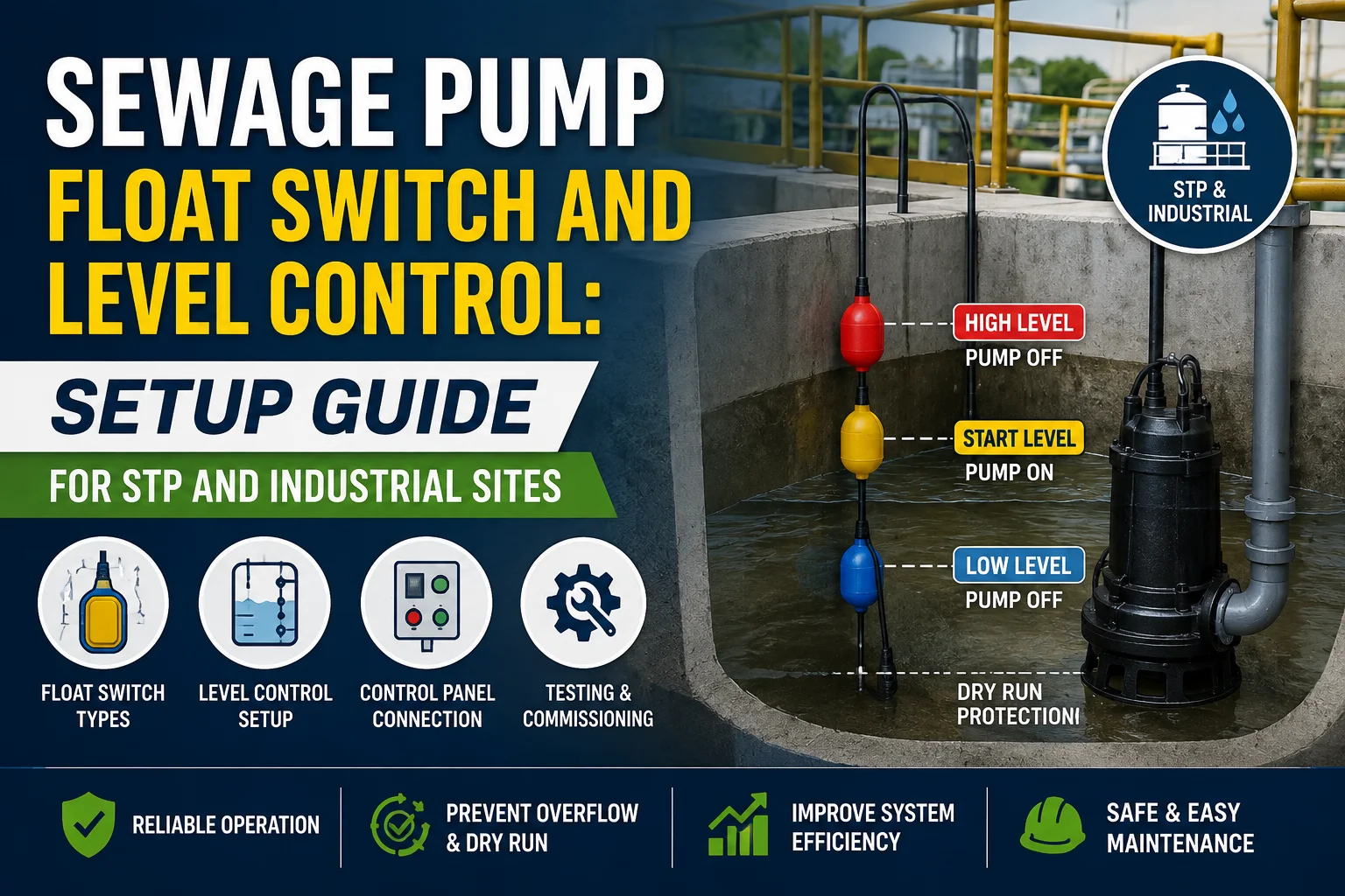
Learn sewage pump float switch setup, wiring, and level control methods for STP and industrial sites to improve reliability, safety, and automation. (153 c
A sewage pump float switch is usually the fastest and most dependable way to automate a submersible sewage pump in a wet well or sump.
It works by opening or closing a contact when the liquid rises or falls to a preset point.
For most STP and industrial drainage applications, the basic layout includes:
- one float for pump ON,
- one float for pump OFF,
- one high-level alarm float,
- and, in multi-pump stations, one or more additional floats for duty/standby changeover.
If the application has turbulent inflow, grease, ragging, or heavy solids, the float arrangement must be set with enough separation so the pump does not short-cycle.
A good setup depends on three things:
- the geometry of the wet well,
- the type of sewage or wastewater,
- and the control philosophy of the panel.
In simple systems, a float switch for submersible pump control is often better than a more complex sensor because it is easy to install, easy to understand, and easy to replace.
In larger stations, float switches are often used together with a sewage pump level sensor, pump run feedback, and alarm logic so the panel can protect the pump and alert operators.
The practical rule is simple:
- use floats for dependable switching,
- use alarms for visibility,
- and use panel logic for protection and alternation.
If you need a broader panel design context, see the control-panel guide at article 47.
For wet-well sizing and float spacing decisions, the wet-well guide at article 52 is also useful.
When the pump itself must handle fibrous solids or difficult sludge, review the submersible sewage sludge pump page.
Why level control matters for sewage pumps
Level control is not just about switching a pump on and off.
It affects hydraulic stability, motor life, alarm reliability, and maintenance frequency.
In sewage and wastewater stations, a small mistake in level control can create recurring problems such as:
- dry running,
- overflow,
- excessive starts per hour,
- blocked suction conditions,
- floating cable damage,
- and nuisance alarms.
A sewage pump float switch helps keep the pump within a usable operating band.
That band should be wide enough to avoid rapid cycling but narrow enough to keep the wet well from filling too high.
In STP and industrial sites, the liquid level is rarely steady.
Influent may arrive in pulses.
The chamber may foam.
Solids may move in clumps.
That is why level control has to be designed for real site conditions instead of ideal laboratory conditions.
Good level control gives the operator four benefits:
1. predictable pump starts and stops, 2. lower electrical and thermal stress on the motor, 3. fewer overflow events, 4. and clearer maintenance diagnostics.
For installation teams, the level-control system also reduces guesswork.
A properly placed float tells the panel exactly when to start pumping and when to stop.
An alarm float adds a second layer of protection if the duty pump does not respond.
In a sewage pump level control strategy, the control panel should not rely on one signal only.
A single device can fail, get stuck on a cable, or become fouled by debris.
That is why most good systems combine:
- float-based switching,
- overload protection,
- motor protection,
- and an audible/visible alarm.
This layered approach matters even more in industrial areas where downtime can affect sanitation, production, or compliance.
For example, in an STP handling mixed wastewater, a failed level device can quickly lead to backflow into upstream chambers.
In a plant drainage pit, it can flood a floor, damage equipment, or force an emergency shutdown.
The cost of better level control is usually small compared with the cost of a single overflow incident.
That is why engineers should treat the float switch as part of the protection system, not as a trivial accessory.
Types of float switches used in sewage pumping
Not every float behaves the same way.
The correct choice depends on the wet-well size, the number of pumps, the type of sewage, and the required control logic.
1. Cable float switch
This is the most common sewage pump float switch.
It is suspended on a cable and changes state when it tilts with the liquid level.
Cable floats are popular because they are simple, rugged, and easy to adjust.
They are often used for:
- single pump start/stop control,
- high-level alarm,
- and basic duplex stations.
2. Mercury-free tilt float
These are similar in function to cable floats but use a safer internal mechanism instead of mercury.
They are commonly preferred in modern systems because they meet current environmental expectations.
3. Vertical float switch
A vertical float switch moves up and down on a guide rod.
It is useful where the chamber is narrow or where space is limited.
It is less common in large sewage chambers but can be helpful in compact pits.
4. Multi-float array
This is a group of separate floats used for start, stop, lead pump, lag pump, and alarm logic.
This arrangement is common in duplex and triplex sewage pumping stations.
It allows the panel to do more than simply switch one pump.
5. Sewage pump level sensor with panel logic
Some sites use an electronic level sensor instead of, or alongside, floats.
This may be an ultrasonic, pressure, or conductive device.
Even when a sensor is used, floats are often retained for backup alarm or independent protection.
Choosing the right type
A simple rule helps:
- choose a cable float for straightforward STP and sump control,
- choose a multi-float arrangement for duplex alternation,
- choose a sensor only when the application needs more precise monitoring,
- and choose a hybrid design when uptime matters most.
If the site has rag-heavy sewage or clog-prone sludge, the float arrangement must stay clear of turbulence zones and inlet splash.
The device should move freely without getting caught on pipes, ladders, brackets, or guide rails.
That is why the physical layout matters as much as the electrical wiring.
Float switch wiring basics
The wiring approach depends on whether the float is being used for direct pump control, panel input, alarm input, or interlock logic.
Most sewage pump float switch installations follow a dry-contact logic path into a control panel.
That means the float does not power the motor directly.
Instead, it sends a signal to the panel, and the panel controls the starter, contactor, or relay.
Typical single-pump logic
For a simple station:
- the low-level float may stop the pump,
- the high-level float may start the pump,
- and the alarm float may trigger when the level rises above the normal band.
Typical duplex logic
For two pumps:
- one float may call Pump 1,
- another float may call Pump 2,
- and a high alarm float may signal that the chamber is rising faster than the system can discharge.
Practical wiring notes
- Keep float cable routing neat and supported.
- Avoid sharp bends near the entry point.
- Separate signal wiring from power wiring where possible.
- Label every float at both the wet well and the panel.
- Check whether the float is normally open or normally closed in the intended position.
- Verify the wiring logic before filling the chamber.
Panel-side protection
Even the best float switch for submersible pump control should be paired with:
- overload relay protection,
- short-circuit protection,
- manual/auto selector logic,
- phase failure protection where relevant,
- and alarm indication.
If a float is wired incorrectly, the pump may run continuously, fail to start, or stop too early.
That is why commissioning should include a dry test before live operation.
Commissioning sequence
A safe commissioning sequence usually includes:
1. inspect the mounting and cable path, 2. confirm the electrical diagram, 3. test continuity of each float, 4. simulate level changes manually, 5. verify start, stop, and alarm responses, 6. and finally observe wet operation.
If the floats are reversed in the logic, the system may appear to work during a quick test but fail under real inflow.
That is one of the most common causes of field callbacks.
A note on cable length
Cable length should allow the float to travel freely without being so long that it tangles.
Extra cable should be secured properly.
Loose cable loops are a common source of fouling in sewage applications.
Multi-pump alternation with float switches
Many STP and industrial installations need more than one pump.
In those cases, float switches are often used to support automatic alternation.
Alternation spreads operating hours across pumps and helps keep one pump ready as standby.
Why alternation matters
If only one pump runs all the time, it will wear faster than the standby unit.
Alternation helps:
- balance run hours,
- reduce maintenance skew,
- keep both pumps exercised,
- and avoid a dead standby pump that has not run for months.
Common alternation methods
#### 1. Time-based alternation
The panel changes the lead pump after each cycle or after a set time.
This is easy to configure but still depends on correct level inputs.
#### 2. Level-based alternation
The panel chooses which pump starts based on the sequence of float inputs.
This is common when a group of floats is assigned to distinct levels.
#### 3. Duty/standby with lag pump
One pump handles normal flow.
The second starts only when the level continues rising or the duty pump fails.
This is a very common and practical design.
Example duplex sequence
A simple duplex setup may work like this:
- first rise: Pump A starts,
- next cycle: Pump B starts,
- rising further: lag pump also starts,
- highest level: alarm is triggered.
The actual logic can vary by panel design, but the principle is the same: the floats create a level ladder, and the panel decides which pump to run.
Important design tip
Keep sufficient vertical distance between the floats.
If the switch points are too close together, the pumps may short-cycle.
Short-cycling increases starts per hour and can overheat the motor.
When alternation is especially useful
Use alternation when:
- the site runs continuously,
- maintenance access is limited,
- the chamber receives irregular inflow,
- or pump redundancy is part of the site’s reliability strategy.
For a larger station, the wet-well design must support the chosen float elevations.
That is why level control should be planned with the chamber geometry, not added after construction.
Ultrasonic and pressure sensors vs float switches
Float switches are not the only way to measure sewage level.
Some projects use ultrasonic sensors, pressure transducers, or conductive probes.
Each option has strengths and weaknesses.
Float switches
Pros:
- simple,
- inexpensive,
- easy to replace,
- visible operating logic,
- suitable for dirty wastewater.
Cons:
- moving parts,
- cable fouling risk,
- less precise than electronic sensing.
Ultrasonic sensors
Pros:
- non-contact measurement,
- good for clean geometry,
- useful when there is no desire for submerged moving parts.
Cons:
- can be affected by foam,
- may struggle in heavy vapour,
- can be confused by turbulence or irregular chamber shapes.
Pressure sensors
Pros:
- direct level measurement,
- can be integrated with telemetry,
- useful for continuous data.
Cons:
- can foul in dirty sewage,
- may require more maintenance,
- can be more expensive than floats.
Conductive or probe-based sensors
Pros:
- useful in some industrial liquids,
- can support multi-point logic.
Cons:
- not always ideal for sticky sewage or sludge,
- can be affected by deposits.
Which is best for STP and industrial sewage?
For most sewage pump level control applications, floats remain the default choice because they are robust and easy to understand.
For advanced monitoring, electronic sensors can be added to improve data visibility.
The strongest solution is often hybrid:
- floats for dependable switching,
- sensor feedback for monitoring,
- and panel alarms for operator response.
In difficult wastewater, simplicity often wins.
A device that is easy to service will usually outperform a more advanced device that is difficult to keep clean.
That is especially true where ragging, grease, silt, or floating solids are common.
Common float switch installation mistakes
Most float switch failures are not caused by the float itself.
They are caused by poor installation, bad spacing, or weak commissioning.
1. Placing floats too close together
If the ON and OFF points are too near, the pump will cycle too frequently.
That increases wear and can trip protections.
2. Ignoring turbulence near the inlet
Floats placed directly in the inflow stream can chatter when the level is still stabilising.
They should be positioned where the water surface is calmer.
3. Cable tangling
Loose float cables can wrap around ladders, pipes, or each other.
This prevents correct movement and causes false switching.
4. Wrong float orientation
Some floats behave differently depending on the tilt angle or installation direction.
If orientation is wrong, the switch point shifts.
5. No independent high-level alarm
A control float should not be the only protection.
A separate alarm float gives the operator a second line of defence.
6. No lead/lag logic in duplex stations
In a multi-pump system, failing to plan alternation can overwork one pump.
It also reduces redundancy.
7. Unprotected wiring paths
Cables in wet, corrosive, or abrasive areas need proper routing and gland sealing.
Poor cable protection leads to insulation damage and signal failure.
8. No dry testing before filling
Commissioning without testing the logic is a mistake that often leads to false confidence.
The panel should be checked before the chamber is put into service.
9. Forgetting maintenance access
If operators cannot reach the floats safely, the system will not be maintained.
Serviceability should be part of the design.
10. Using the wrong device for the liquid
Not every sensor is suitable for raw sewage.
The choice must match the actual fluid condition, solids load, and cleaning frequency.
A practical site rule
If you are unsure about the best mounting position, choose a layout that prioritises free float movement, clear separation, and easy maintenance access.
That approach prevents most field issues before they start.
Frequently asked questions
1. What does a sewage pump float switch do?
It tells the pump when to start and stop based on liquid level. In a sewage or wastewater chamber, the float moves with the rising or falling water and sends a switching signal to the control panel.
2. Is a float switch better than a level sensor for sewage pumps?
For many STP and industrial sites, yes. A float switch for submersible pump control is simple, rugged, and easy to maintain. A sensor can be useful for advanced monitoring, but floats are usually easier to keep working in dirty wastewater.
3. How many floats do I need for a sewage pump station?
That depends on the site. A single pump may use a start float, stop float, and alarm float. A duplex station may need additional floats for alternation and lag pump control.
4. Can one float control both start and stop?
In some basic installations, yes, but it is usually better to separate the logic. Separate start, stop, and alarm points reduce nuisance cycling and improve reliability.
5. Why does my sewage pump keep cycling on and off?
The floats may be too close together, the chamber may be too small, or the inflow may be turbulent. It can also happen if the pump capacity is too high for the wet-well volume.
6. How do I stop floats from failing in sewage?
Use the right float type, keep the cables clear, avoid inlet turbulence, provide maintenance access, and test the system regularly. A good installation often matters more than the brand name.
Need help selecting the right pump?
Share your flow, head, liquid type, solids, site layout and duty cycle with Flow Chem Pumps. Our team can help you shortlist the right pump.